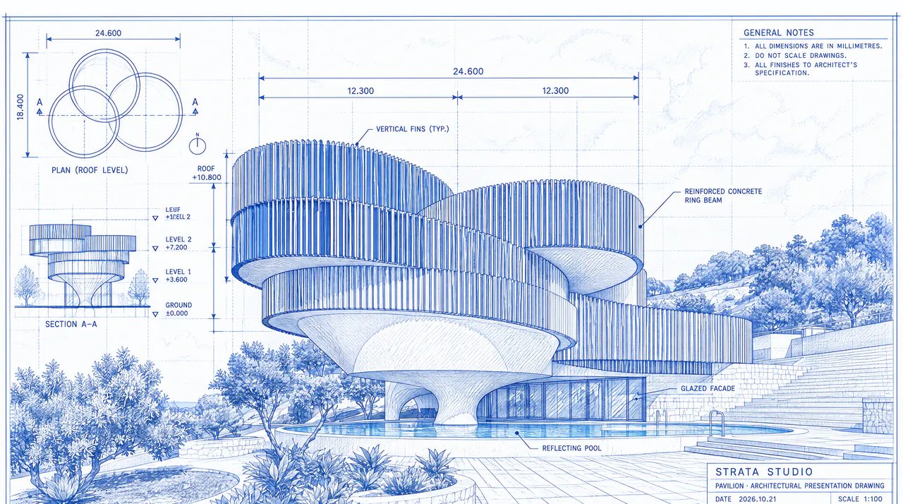
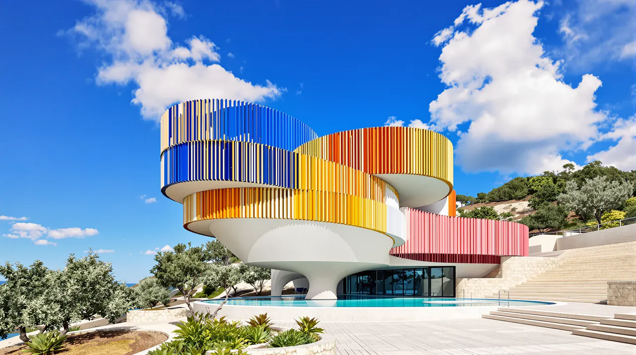
A white concrete house of stacked round floors, each wrapped in vertical fins in blue, yellow, orange and pink, above a pool and stone terraces on a wooded hillside.

Strata Build

From drawing to reality...

Projects

Six jobs in London and Porto. We designed and built each one.

  1. 01Casa Mar Type: 42 flats, place: Matosinhos, year: 2027 On site

    22 storeys on the seafront. Every flat runs from the street to the sea. Figs. 1 to 4.

  2. 02Lea Bridge Yard Type: Workshops and flats, place: London, year: 2026 In planning

    Ground-floor workshops with 18 flats above, on a former timber yard. Application in at the end of RIBA stage 3. No drawings shown.

  3. 03Mast Gallery Type: Gallery, place: Porto, year: 2025 Complete

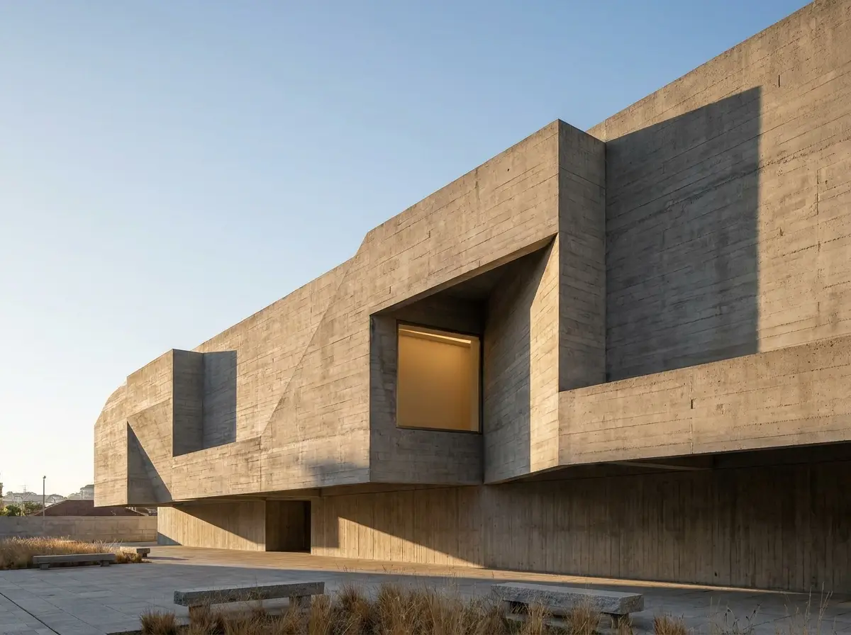
    Board-marked concrete on a sloping quay, poured in four lifts by our own formwork crew. Figs. 5 and 6.

  4. 04The Calder House Type: House, place: London, year: 2024 Complete

    An L-shaped house behind an Islington mews, built round an old olive tree. Figs. 7 and 8.

  5. 05Albion Mews Type: Roof extension, place: London, year: 2023 Complete

    A timber-framed top floor added to a conservation-area mews house, built in five weeks. No drawings shown.

  6. 06Rua do Almada Type: Shop and workshop, place: Porto, year: 2023 Complete

    A ground-floor shop refit with our joinery workshop behind it. No drawings shown.

How we work

Design

One team from the first survey to the last snag. No hand-off between drawing office and site.

Price

We price from finished drawings, before anyone digs, and show you every line of the cost plan.

Change

If something changes on site, you get the new drawing and the new cost in the same week.

1:80INTERNALEXTERNALFFL +4.500+4.490B902501701601100 MIN802400123456111379810120500 mmLevels at L1, above L0 FFL ±0.0001Timber floor 202Screed 65, acoustic layer 53Concrete slab 2504Sliding door, insulated sill5Thermal break 80, bars through6Slab cast to falls, 1:80 min7Level threshold: slot drain8Tiles 20 on A1 pedestals9Membrane, sealed under sill10Drip trim, membrane lapped on11Shoe side-fixed below membrane12Laminated glass guard13Shoe cap, drip 20 past shoeSTRATACASA MAR · DETAIL 1, BALCONY EDGED-3101:10 @ A1ConstructionRev C114.10.2026Drawn SSChecked ASConcept siteINTERNALEXTERNAL+4.500B902501100 MIN802400123456111379810120500 mmLevels at L1, above L0 FFL ±0.0001Timber floor 202Screed 65, acoustic layer 53Concrete slab 2504Sliding door, insulated sill5Thermal break 80, bars through6Slab cast to falls, 1:80 min7Level threshold: slot drain8Tiles 20 on A1 pedestals9Membrane, sealed under sill10Drip trim, membrane lapped on11Shoe side-fixed below membrane12Laminated glass guard13Shoe cap, drip 20 past shoeSTRATABALCONY EDGED-3101:10 @ A1ConstructionRev C114.10.2026Drawn SSChecked ASConcept site
Fig. 1 Casa Mar, balcony edge Sheet D-310 · 1:10 · 2026 · Construction · Drawing: Studio Scardthomas
Describe this drawing

A section through the edge of a floor where it meets the balcony. Inside, the concrete slab carries screed and a timber floor, with a sliding door on top. A block of insulation, drawn in blue, separates the inside slab from the balcony slab so heat does not leak out. The balcony slab is cast to fall 1 in 80 towards its edge, under a waterproof membrane. The membrane is sealed under the door sill, and a slot drain sits in front of the door, so the threshold can be level. Tiles sit on adjustable pedestals. At the edge, the membrane laps onto a drip trim. The glass balustrade, at least 1100 mm high, sits in a metal shoe fixed to the face of the slab below the membrane, so no bolt goes through it. The drip trim laps onto a cap over the shoe, sealed to the glass, and the cap ends in a drip lip 20 mm out from the shoe, so water falls clear of it. The pedestals are non-combustible (class A1). The balcony is drawn with a break: it is 2.4 m deep from grid B, as on the floor plan. Levels are at level 1. Numbered notes 1 to 13, in hexagons, name each part.

Visualisation

Stage 2 of 4, now Frame Stage 1, basement and core, done
Stage 3 of 4, Dec 2026 to Mar 2027 Glass and
balconies
To be fixed from inside each floor
Planned, Mar 2027 Closed in. Next, stage 4 of 4: handover, spring 2027

Visualisation

Casa Mar, Matosinhos

Street to
sea.

42 flats on 21 floors. Every flat has windows on both sides and a 2.4 m balcony over the Atlantic. First keys spring 2027.

Casa Mar, Matosinhos

The drawings behind it

We draw the build before we start it. The elevation, the four build stages at one scale, and the typical floor. The blue line is where the work is now.

123456Top +74.650Roof +70.650L21 +67.500L11 +36.000L1 +4.500L0 ±0.00021 × 31504000450074 650 overall22 400010 mLevels in metresabove L0 FFL (ground)STRATASEA ELEVATION, WESTA-2011:200 @ A1ConstructionRev C102.09.2026Drawn SSChecked ASConcept site123456Top +74.650Roof +70.650L21 +67.500L11 +36.000L1 +4.500L0 ±0.00021 × 31504000450074 650 overall22 400010 mLevels in metresabove L0 FFL (ground)STRATASEA ELEVATIONA-2011:200 @ A1ConstructionRev C102.09.2026Drawn SSChecked ASConcept site
Fig. 2 Casa Mar, sea elevation Sheet A-201 · 1:200 · 2026 · Construction · Drawing: Studio Scardthomas
Describe this drawing

The seaward face of the 22-storey block (a ground floor and 21 floors of flats), 22.4 m wide, 70.65 m to the roof and 74.65 m to the top of the roof pavilion. Every flat floor (level 1 to level 21) has a 2.4 m balcony with a glass balustrade. A pale grey band under each balcony is its shadow on the wall behind, which shows the depth. The glazed pavilion on the roof is 4 m tall; its lower part is hidden by the parapet and drawn dashed. Levels are marked from L0 (the ground floor, ±0.000) to level 1, level 11, level 21, the roof and the top of the pavilion, with the 4.5 m ground storey and 21 floors of 3.15 m dimensioned on the right. A tree and two people at the base show the scale.

  1. L0L4020 mSTAGE 1Done

    1. Basement and core Mar to May 2026 Done

    Piles and basement walls. The concrete core goes first and stays three floors ahead of the frame.

  2. L0L11020 mSTAGE 2Now

    2. Frame Jun to Nov 2026 Now

    One flat slab a week. Level 11 poured in October; edge protection rides one floor up.

  3. L0L14020 mSTAGE 3Next

    3. Glass and balconies Dec 2026 to Mar 2027 Next

    Frame tops out. Glazing follows from level 1, fixed from inside each floor.

  4. L0Top020 mSTAGE 4Planned

    4. Handover Spring 2027 Planned

    Crane off site. Snagged floor by floor, then keys.

STRATACASA MAR · CONSTRUCTION SEQUENCEC-0011:1000 @ A1Construction, now at stage 2 of 4Rev C314.10.2026Drawn SSChecked ASConcept siteSTRATABUILD SEQUENCEC-0011:1000 @ A1Construction, now at stage 2Showing stage 1 of 4Rev C314.10.2026Drawn SSChecked ASConcept site
Fig. 3 Construction sequence, four stages Sheet C-001 · 1:1000 · 2026 · Construction, now at stage 2 of 4 · Drawing: Studio Scardthomas
Describe this drawing

Four side-by-side elevations of the same 22-storey block, drawn at one scale, under one title block for sheet C-001. Stage 1: the basement and the concrete core up to level 4, with a tower crane. Stage 2: the concrete frame up to level 11, the core three floors ahead, and the floor being poured marked in blue. Stage 3: the frame finished with the roof pavilion, and glazing up to level 14. Stage 4: the finished building with glass on every floor, no crane, a tree and two people at the door.

Typical floor

Every flat runs from the street to the sea.

Two flats on each floor share a core with two stairs and two lifts, so there is no corridor. Every one of the 42 flats has windows on both sides.

Bedrooms face the quiet street. The living room opens onto a 2.4 m balcony over the Atlantic. On site since March 2026.

Bed 1Bed 2BathHallLiving / kitchenFlat ABalconyBed 1Bed 2BathHallLiving / kitchenFlat BBalconyUPDNUPDNStair 1Stair 2LobbyFF liftLiftSV123456AB1000260018002000800600080020001800260010004650355060003550465082006000820022 40010 400240012 800STREET37502650265037501D-310SEAFFL L1 +4.500Outer flights go up, inner flights down.Arrows show travel from this floor.FF: firefighting lift, car 1100 × 1400.SV: smoke shaft 2.8 m².Wet riser outlet, one per stair.Flats: protected hall, FD20 hall doors.Flat entrance doors FD30S, self-closing.All flat doors 926 leaf, 1000 opening.Piers 800 at the core (street), 600 (sea).Levels above L0 FFL ±0.000.05 mNSTRATACASA MAR · TYPICAL FLOOR, L1 TO L21A-1101:100 @ A1ConstructionRev C214.10.2026Drawn SSChecked ASConcept site12345612345687891011AB123456SEASTREET4650355060003550465022 400240010 400+4.5001Bed 12Bed 23Bath4Living / kitchen5Balcony6Hall7Lobby8Stairs 1 and 29Firefighting lift10Lift11Smoke shaftWet riserOuter flights up, inner down.Arrows show travel from this floor.Openings (mm), each flat:street windows 2600 and 2000,sea doors 3750 and 2650.Hall doors FD20, 926 leaf;entrance FD30S, self-closing.Level shown: L1 FFL, above L0.05 mNSTRATATYPICAL FLOORA-1101:100 @ A1ConstructionRev C214.10.2026Drawn SSChecked ASConcept site
Fig. 4 Typical floor, levels 1 to 21 Sheet A-110 · 1:100 · 2026 · Construction · Drawing: Studio Scardthomas
Describe this drawing

The block is 22.4 m wide and 10.4 m deep. The street is at the top and the Atlantic at the bottom. The block is over 18 m tall, so the core has two protected stairs side by side on the street side. A small lobby serves both flats, with a firefighting lift, a second lift and a smoke shaft, 1.4 by 2.0 m, on the sea side. Each stair has landings 1350 mm deep, more than its 1300 mm flight width, and a wet riser outlet on the floor landing, because the top floor is over 50 m up. In each stair the outer flight goes up and the inner flight goes down. The door from the lobby swings 900 mm onto the floor landing and leaves 450 mm clear in front of the top step. Flat A is on the left and Flat B on the right, each a mirror of the other. The flat door opens off the lobby into a protected entrance hall. Every room opens off this hall: the two bedrooms on the street side, the bathroom, and the living room and kitchen, which runs across the sea side, with the kitchen on the end wall. Every flat door is a 926 mm leaf in a 1000 mm opening, drawn at its true width with its full swing. The flat entrance door is FD30S and self-closing; the doors off the hall are FD20. A 2.4 m deep balcony runs the full width on the sea side, split between the two flats. Grid lines 1 to 6 and A to B, dimensions in millimetres, the width and position of every window and sliding door, and the balcony detail 1 (Fig. 1) are marked.

Two projects

Each one shown, then drawn.

Board-formed concrete art gallery facade with deep geometric shadows
Fig. 5 Mast Gallery, quay front Porto · 2025 · Concept image

Mast Gallery

Gallery · Porto · 2025

A public gallery on a sloping quay. The walls were poured in four lifts so the board lines run unbroken round every corner.

1234+12.000+10.500+7.500+3.000±0.000−3.20030003000300030001346725300010 50012 00010 50036 0001Board-marked concrete, gallery2Ground storey set back, in shadow3Picture window, splayed reveal4Recess cut into the parapet5Entrance6Shadowed recess, east block7Pour joint, lifts of 3 mBoardsGraniteShadow, 45°05 mLevels in metres from entrance FFL ±0.000STRATAMAST GALLERY, PORTO · SOUTH ELEVATION, QUAYA-2001:100 @ A1As builtRev C411.06.2025Drawn SSChecked ASConcept site1234+12.000+7.500+3.000±0.000−3.2001346725300010 50012 00010 50036 0001Board-marked concrete, gallery2Ground storey set back3Picture window, splayed reveal4Recess cut into the parapet5Entrance6Shadowed recess, east block7Pour joint, lifts of 3 mBoardsGraniteShadow05 mLevels from entrance FFLSTRATAELEVATIONA-2001:100 @ A1As builtRev C411.06.2025Drawn SSChecked ASConcept site
Fig. 6 Mast Gallery, south elevation Sheet A-200 · 1:100 · 2025 · As built · Drawing: Studio Scardthomas
Describe this drawing

The gallery seen from the river, as in the photo above. The ground storey is set back in shadow, with vertical board marks and the entrance near the left. Above it, the gallery oversails the whole front in horizontal board-marked concrete, poured in four 3 m lifts, dimensioned up the east end. Its parapet is low at the rounded west end, with a slot cut into it, then slopes up to a taller middle with a square picture window set deep in a splayed reveal. A taller east block on the right has a large recess in shadow. Grey tone marks shadow. The quay is level with the entrance, at ±0.000, with the river below. Grid lines are numbered in circles; notes 1 to 6 are numbered in hexagons and named in the key.
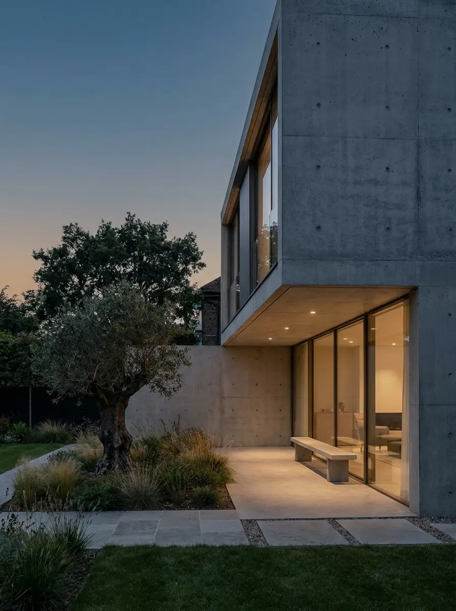
Minimalist concrete-and-glass house at dusk with warm interior glow
Fig. 7 The Calder House at dusk London · 2024 · Concept image

The Calder House

House · London · 2024

A house behind a mews in Islington. The olive tree stayed, so the footings were set out around its roots.

HallShowerKitchenLivingStudyBed 1Bed 2CourtyardUPMEWSOlive tree,keptRoot zone, no digging±0.000−0.1501234ABC54004200480014 4008200160018001600180016001000720010 40017 600220010003200220020002800100022002800220021002700120012001200Beam 7200Pad footing, outside root zoneBridging beam, no dig, below floorBrick wall05 mLevels in metres from hall FFL ±0.000NSTRATATHE CALDER HOUSE · GROUND FLOORA-1001:100 @ A1As builtRev C320.03.2024Drawn SSChecked ASConcept site12345678UPMEWS910±0.000−0.1501234ABC54004200480014 400720010 40017 60072001Hall2Shower3Kitchen4Living5Study6Bed 17Bed 28Courtyard9Olive tree, kept10Root zone, no diggingOpenings (mm): front door 1000,corridor windows 1200, bedroomand study windows 1600, kitchenwindows 2200 and 2100, livingwindows 2800, sliding doors 2700.Pad footing, outside root zoneBridging beam, no digBrick wall05 mLevels from hall FFLNSTRATAGROUND FLOORA-1001:100 @ A1As builtRev C320.03.2024Drawn SSChecked ASConcept site
Fig. 8 The Calder House, ground floor Sheet A-100 · 1:100 · 2024 · As built · Drawing: Studio Scardthomas
Describe this drawing

An L-shaped house. A gate from the mews at the top leads to the front door, which opens into the hall with the stair and a shower room. From the hall, a door leads to the kitchen and on to the living room; both run across the top. A corridor runs down the left wing beside the courtyard wall, with a door to the study and to each of the two bedrooms. Sliding glass doors open from the living room onto the courtyard, which fills the rest, with the old olive tree in the middle. A blue dashed circle marks its root zone, where nothing was dug. The wall over the roots sits on a bridging beam, drawn in blue, cast on formwork laid on the ground so nothing is dug. It spans 7.2 m to two pad footings that sit fully outside the root zone. The beam and footings are below the floor, so they are drawn dashed. The width of every outside door and window is dimensioned; the inside doors are not.

Process

Seven steps, each one a stage of the RIBA Plan of Work 2020. You see a drawing at the end of every step.

  1. Flats42Flat floors21Bedrooms2B-001Schedule RIBA 0 and 1

    Brief

    What you need, what you can spend, and when.

  2. S-001Survey RIBA 1

    Site

    Measured survey, levels, trees and services.

  3. ABCSK-010Massing RIBA 2

    Concept

    Two or three massing options in sketch and card model.

  4. A-201Elevation RIBA 3

    Planning

    Coordinated drawings. The planning application goes in at the end of this stage.

  5. D-310Detail RIBA 4

    Technical

    Construction details and the full cost plan, line by line.

  6. C-001Stage 2 RIBA 5

    Build

    Our own site team builds from our own drawings. Fig. 3

  7. A-110Snags RIBA 6 and 7

    Handover

    Keys, manuals, then visits at six and twelve months.

Fig. 9 Casa Mar, one sheet from each stage Sheets B-001 to A-110 · Reduced, not to scale · 2026 · Drawing: Studio Scardthomas
Describe these sheets

Seven small sheets from the same job, one per stage. Brief: the schedule, 42 flats on 21 floors. Site: the survey with the boundary in blue. Concept: three massing options, with the slim tower circled. Planning: the sea elevation as issued for planning (Fig. 2 is its later construction issue). Technical: the balcony edge, as in Fig. 1. Build: stage 2 of the sequence in Fig. 3. Handover: the typical floor from Fig. 4, with two snags marked.

Concept example, not a real fee. Each design stage has a fixed fee, agreed before it starts. The build is priced from the stage 4 drawings, so the cost plan is fixed before work starts on site.

What we do

One contract covers the drawings and the build. One person answers your calls from the first survey to the last snag.

  • Design and planning

    Surveys, planning drawings, building regs and the structural engineer.

  • New build

    Houses, flats and mixed-use blocks.

  • Extensions and refits

    Rear and roof extensions, basements, listed and conservation-area work.

  • Exposed concrete

    Our own formwork crew, for board-marked and fair-faced finishes.

  • Joinery

    Kitchens, stairs and fitted furniture, made in our Porto workshop.

  • Aftercare

    We come back at six and twelve months to fix anything that has moved.

Got a site, or a set of drawings?

Send the address and a line about what you want to build. An architect will reply with what we would check first.

Marta Lobo

Partner and architect. Answers every new enquiry.

Email
marta@strata.example
Phone
+44 20 0000 0000[placeholder]
London
Studio, Clerkenwell EC1[placeholder address]
Porto
Workshop, Porto[placeholder address]

Fictional person and firm. These details do not reach anyone.